
Description
Package Content:
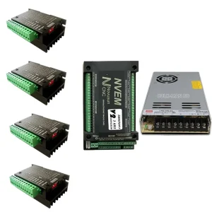
1x HBS57 Stepper Motor Drive
1x 24V Fan
1x GX16-4P Male connector with wiring
1x GX12-6P Male connector with wiring
2 Core DC Power Cable Cable 22AWG 0.5m
2 Core DC Power Cable Cable 20AWG 0.5m
6x 4MM heat shrink tube 10CM
6x 4MM Y-shaped terminal
4x M4-6 Button screw
4x Fan screws
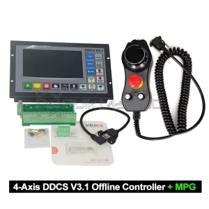
Please note that this 5-axis control box is not a universal five-axis control system. It should be clarified that the DDCS system only supports 4 axes, with the Y-axis and the fifth axis operating in a synchronized motion state. In the DDCS settings, the axis-following function must be disabled to configure the fourth axis as the A-axis. It is recommended to use it in combination with the The 4th Axis with 80mm 4-Jaw Chuck.
- Disable the axis following function in the DDCS settings so that the fourth axis becomes the A-axis.
2. Add a fifth-axis driver and connect its signals in parallel with the Y-axis. Merge the pulse signal wires and alarm signal wires into the Y-axis signal interface.
At this point, the fifth axis will move synchronously with the Y-axis as the Y2 axis.

Reviews
There are no reviews yet.